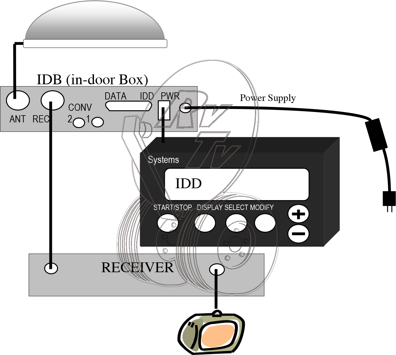
SV-360 Single HD0 without 110 Adapter |
||

|
SV-360 Single HD1 w/110 Adapter |
||
|
|
SV-360 Dual HD0 without 110 Adapter |
||
|
|
SV-360 Dual HD1 w/one 110 Adapter |
||
|
|
SV-360 Dual HD2 w/two 110 Adapters |
||
|
|
In Door Display (IDD) Button Functions |
||||||||||||||||
|
|
Diagram of Parts |
||
|
|
Power Up-Please Wait/Ant Comm Error |
||
|
Fault Description: A “Power Up-Please Wait” or “Antenna Comm Error” occurs when the 24VDC operating voltage generated from the power supply (plugged into a standard 120 volt AC wall outlet) does not reach the CPU board located in the Antenna (upper unit). Possible Cause:
Troubleshooting:
|
EL Fault (Elevation Fault) |
||
Fault Description:An “EL Fault” will occur when the elevation or up and down movement of the antenna is not moving properly or the elevation bias voltage is too high.Possible Cause:
|
AZ Fault (Azimuth Fault) |
||
Fault Description:An “AZ Fault” will occur when the azimuth or circular movement of the antenna is not moving properly or the azimuth bias voltage is too high.Possible Cause:
|
Scan Error |
||
Fault description:A “scan error” will occur if the antenna fails to receive and lock onto the satellite signal.Possible Cause:
|
Lock Verify |
||
Fault Description:A “Lock Verify” usually occurs when the antenna is locked on to the wrong satellite or there is a partial blockage of the satellite signal.Possible Cause:
|
Power Trip/Display Blinks Repeatedly |
||
Fault Description:When turned on the TracStar Display (IDD) reads “Power Trip” or blinks continuously.Possible Cause:
|
Stays in Loading/Load Error |
||
Fault Description: When the antenna is initially turned on or the parameters are changed in the dealer setup menu the antenna goes through a loading sequence. A “load error” may occur if the information from the IDD (display) doesn’t reach the CPU/Gyro board in the antenna during this loading sequence.Possible Cause:
|
Won’t Lock on to Satellite |
||
Fault Description: If the antenna won’t lock onto the satellite, refer to the “Scan error” section for help (see Section 12).
|
Stays in Scan Align |
||
Fault Description:Shortly after turning on the antenna the display will read “scan align” which is the circular movement of the antenna. Within a couple of minutes the display should read “wide scan” which indicates the antenna is moving in a circle and elevating up and down while searching for the satellite signal. If the display stays in “scan align” and never goes to “wide scan” then the antenna will never lock on to the satellite signal.Possible Cause:
|
Missing even odd or no Transponders |
||
Fault Description:Transponders are signals sent from the satellite in the sky to your antenna. These transponders carry your programming to your satellite receiver and allow you to watch different programs. When you are missing transponders as indicated on your satellite receiver transponder menu, you may have difficulty downloading your guide or you may have missing channels or programs that you normally would get.Possible Cause
|
Low Signal Strength |
||
Fault Description:Low signal strength as indicated on the TracStar display, the receiver’s transponder menu, or pixilation of programming on your TV. Low signal strength may prevent the antenna from locking onto the satellite signal or cause programming to come in and out (pixilate).Possible Cause:
|
Locks on to the Satellite Then Loses Signal |
||
Fault Description:The IDD will read “RUN LOCKED S XX” then the signal will drop and the antenna may go back into scan align.Possible Cause:
|
Missing Channels |
||
Fault Description:Some or all of the channels that you normally view are not appearing on the TV.Possible Cause:
|
Antenna does not switch satellites |
||
Fault Description:The antenna doesn’t switch satellites when changing channels on your receiver.Possible Cause:
|
Option 21 reset |
||
The Option 21 reset is used for resetting certain parameters that were originally installed in the antenna at the factory.Procedures:
|
“O” Recalibrate |
||
The “0” recalibrate is used to reinitiate the scan process when the antenna has difficulty finding the satellite signal.Procedures:
|
Show Motion |
||
The Show motion function is used when it is necessary to verify the antenna’s range of motion and speed in azimuth (circle) and elevation (up-down).Procedures:
|
Mechanical Calibration |
||
The Mechanical Calibration is performed at the factory to set the lower and upper elevation parameters. This calibration is rarely needed by the customer.Procedures:
|
Magnetic Calibration |
||
This calibration is used for helping the antenna’s compass compensate for magnetic interferences caused by the different metals built into the coach (RV). Basically this calibration may help the antenna acquire the satellite signal faster.Procedures:The Magnetic Calibration requires the coach to be driven in a complete circle. The circle must be big enough so that at idle speed it will take you 1 1⁄2 minutes to complete the circle.
|
Temperature Calibration |
||
The Temperature Calibration is used when the antenna has difficulty locking on to the satellite due to high bias readings in the diagnostic section of the TracStar display.Procedures:
|
Removal |
||
Required Tools:
Removing your Installed Antenna
|
Installation |
||
|
Motor Replacement |
||
Replacing the Elevation Motor (figure 2)  Required parts:
|
Electronics Replacement |
||
Replacing the electronics (sensor box, CPU, and motor control board figure 3-14)***All components received must be replaced together for proper antenna operation. Turn the power off on the antenna before installing electronics to avoid damage.***Required tools:
|
Single to Dual Upgrade |
||
*NOTE: All steps may not be required or may be slightly different depending on model and/or configuration of your antenna and the dual kit provided.REQUIRED PARTS:
|
Upgrade Software |
||
SV360 Software Update Kit Includes:
|
Figures (Drawings) |
||||||||||||||||||
|
Helpful hints/general knowledge |
|
Glossary of Terms |
||||||||||||||||||||||||||||||||||
|